Distributed Brands
View Catalogue
JRC Spare Parts
Specialising in the design and manufacture of products for commercial workboats and fishing vessels.
Specialising in the design and manufacture of products for commercial workboats and fishing vessels.
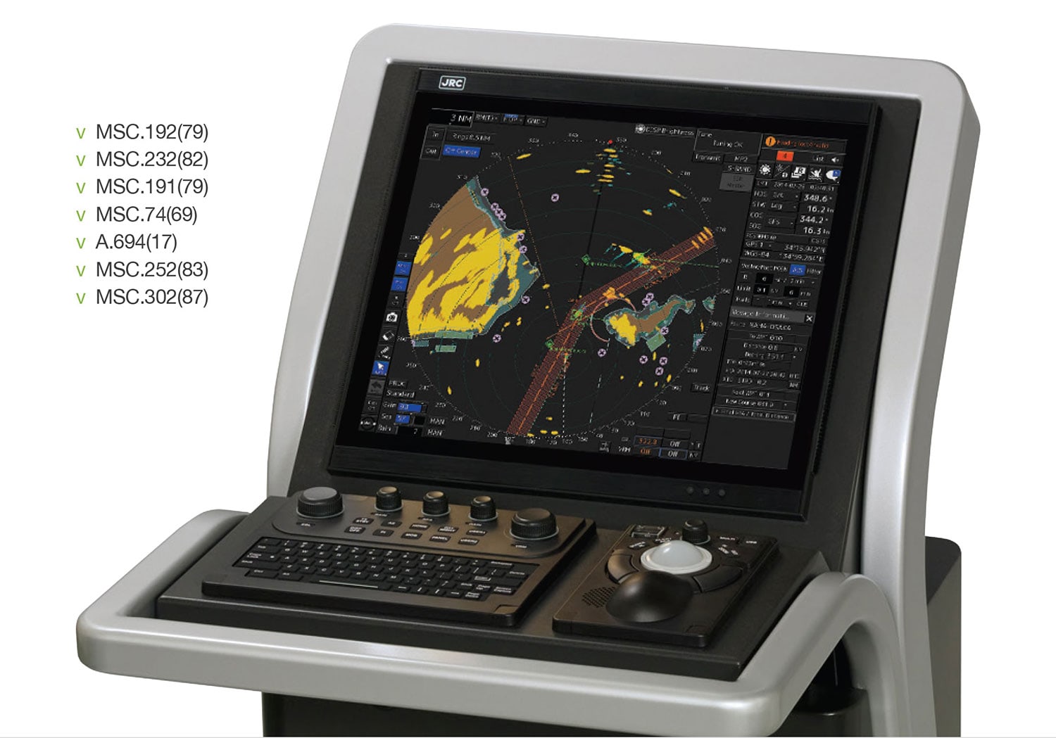
Following many decades of navigation experience and with a wealth of feedback from vessel owners, navigation officers and training institutions around the world, JRC introduces the latest, all-new Multi Function Display (MFD). Underneath the beautifully designed units, the MFD is packed with powerful components that give you smooth graphics, fast processing and all-round serious performance.
And at the same time, the MFD operating system has been developed by JRC engineers to deliver one of the most intuitive and integrated maritime bridge experiences in the world. Our new approach offers an incredibly easy-to-use icon based navigation experience with simple menus and dedicated functions. With a few clicks, you can do things like route planning, acquiring targets, switching between the systems or show alarm information.
Adding new functions along the lifetime of the MFD was the first thought. And will not be an afterthought. With the use of a license system and the assistance of near global communication via satellite, you can welcome new features onboard almost anywhere on the planet.
All-in-all, the MFD is diverse, flexible and relevant to the many different markets and vessel types, it makes navigation dramatically more interactive and intimate than ever before - while keeping no compromise on the quality you expect from JRC.
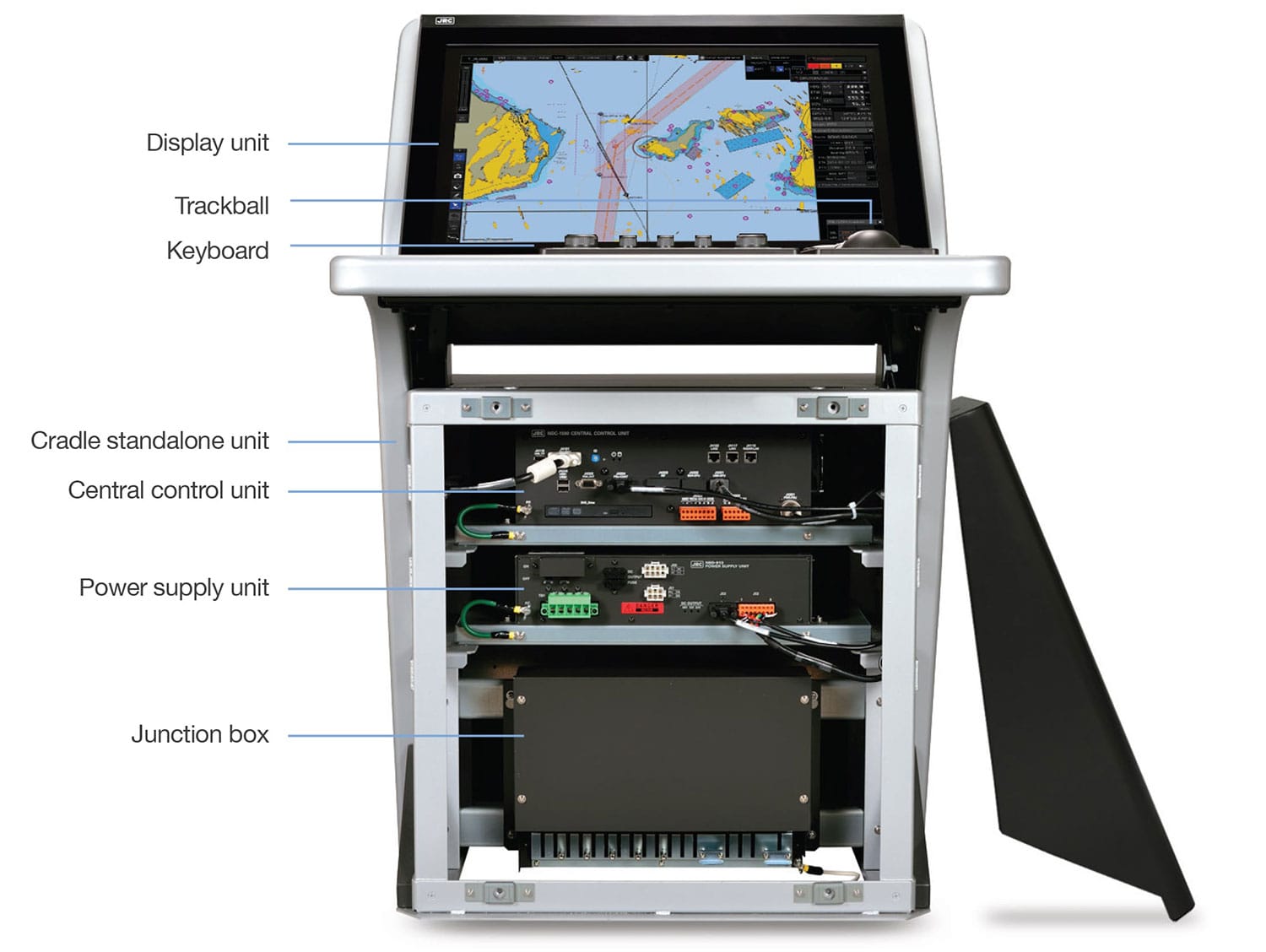
Every aspect of the development of the MFD has been carefully considered. Take for instance the form factor at the heart of the MFD. The processor called the Central Control Unit (CCU), the power supply unit and the junction box are designed with common form factors, so installation is made easy, both as a black box solution or in a standalone unit. In case of a black box installation, simply fit the CCU and power supply on top of each other and place as necessary the junction box close to each, easily and effectively, taking up the least amount of space. This deliberately basic design allows for a uniform, graceful and easy on the eyes approach.
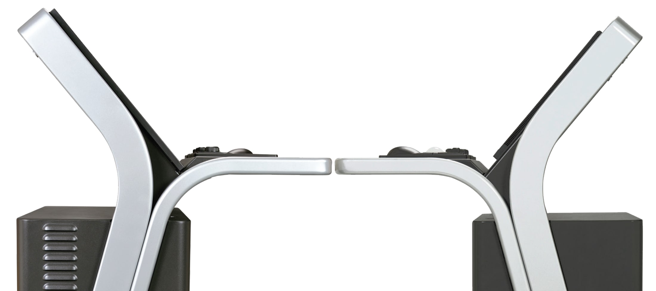
And it really becomes evident when looking at the standalone consoles. The beautiful, minimalist design, available as 19-inch (58cm wide) and 26-inch (68cm wide) variants. Cables are hidden, even on the 26-inch version where it looks like the display is floating. The framework is made from high quality, thick-walled aluminium tubing, formed to a solid piece with soft and elegant corners. Anthracite (code N2.5) color tone is used throughout, including all options and accessories of the MFD platform. Even the box that holds the necessary interfacing is thought through. The design and construction of this level is unmatched. As a result, the MFD standalone console looks and feels unbelievably sleek and strong.
We may not have been the first to the party, but we can be the best. And as the software design team gradually saw the hardware they would develop for, we realized that we had the unique opportunity to redefine our design philosophy and bring harmony between the various products.
During the development process of the MFD we have created a user interface unique to JRC which we call jGUI, which includes a man machine interface design common to all products.
With a vibrant, lively interface and new features that take full advantage of the technology inside, jGUI is made for MFD, and every product it can be. Our software engineers are, and will continue to be, the brains behind probably JRC’s biggest project and product development to date since the founding in 1915.

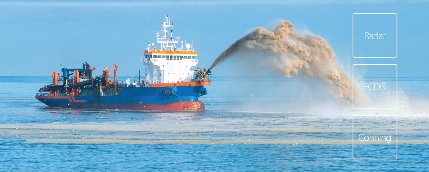
As a leading manufacturer of marine electronics for nearly 100 years, JRC continuously responds to market needs which have resulted in a beautiful, modular and cost-effective platform. The MFD operating system can simply be used as a basic unit for radar, ECDIS or conning or can be extended with the most demanding applications. From standalone models with 19 or 26-inch displays to black box configurations with JRC’s original QWERTY keyboard complete with all the interfacing necessary.
Regardless of how you use it, or which product you select, it all has been designed with a standardized form factor which allows easy assembly and repair, smart production, logistical savings, upgrades and more.
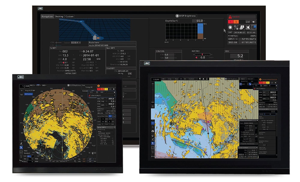
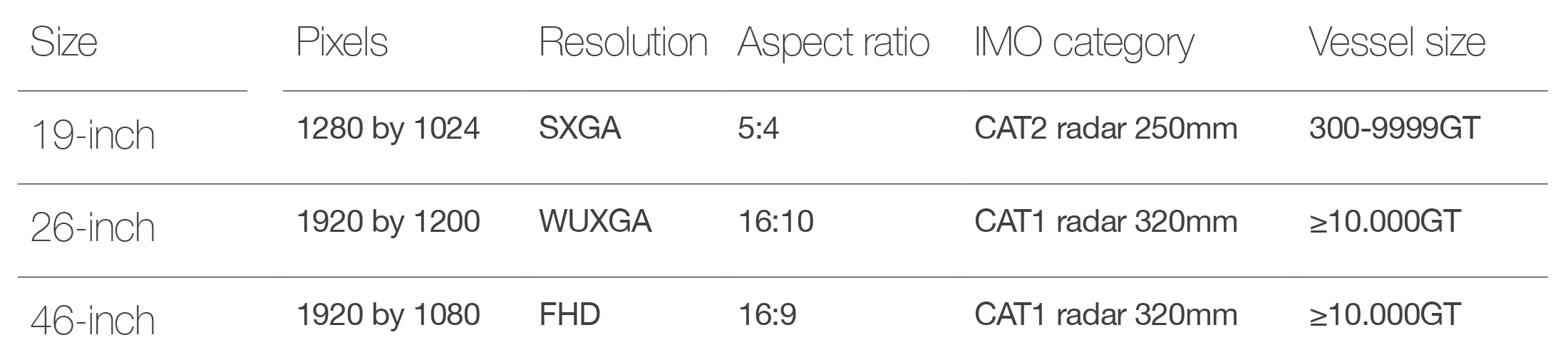
The new MFD can be connected to JRC’s 19-inch and 26-inch proprietary displays. Both displays are completely new following the latest standards and are developed in line with JRC minimalistic design approach. The 19-inch and 26-inch are available as standard LCD or as bonded version. The display fits nicely in the standalone unit, in a similar design desktop frame or as flush mount installation with the screws nicely hidden behind a cover.
Bonding is a process whereby the air gap between the front glass and LCD module is filled with a special compound, significantly enhancing night vision while reducing sunlight reflection and overheating as well as a reduction of possible condensation. The GUI is developed for trackball and/or keyboard as well as touch operation. Needless to say, touch displays are optionally available. For some total bridge solutions display size can be extended up to 46-inch, also compliant with the IMO wheelmark. Alternatively, a range of third party type approved displays may be connected.
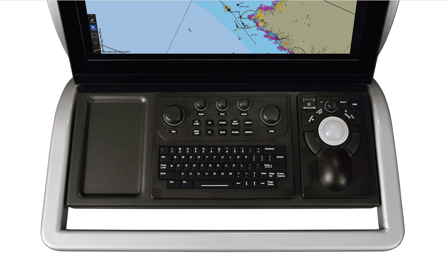
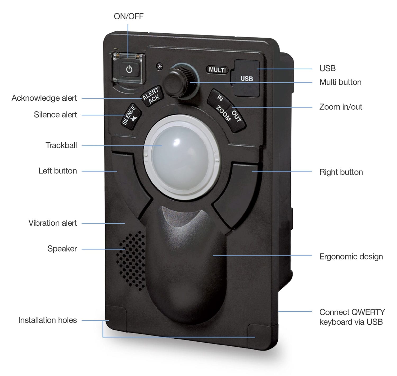
The MFD can be configured as the most complex system with a lot of functions, interfaces and so on, but it all starts with the two base elements: the Central Control Unit (CCU) and the trackball. With the trackball all functions are accessible on screen and also dedicated buttons for silencing the alert buzzer and acknowledge an alert, zooming in and out are readily available.
A smart multi button found on the operating unit allows the operator to “turn and press” to access various functions such as zoom, display and brightness and track color. The function selected at that point is shown at the top center on the display.
Having a USB on the trackball allows you to update the software of the system, import/export various functions such as user maps and even charge appropriate portable devices. The trackball, like the keyboard will be part of the central dimming system used on the bridge. Also in case of an alert, the trackball will change color according to the priority of the alarm and can be set to vibrate similar to a telephone as an additional method of notification.
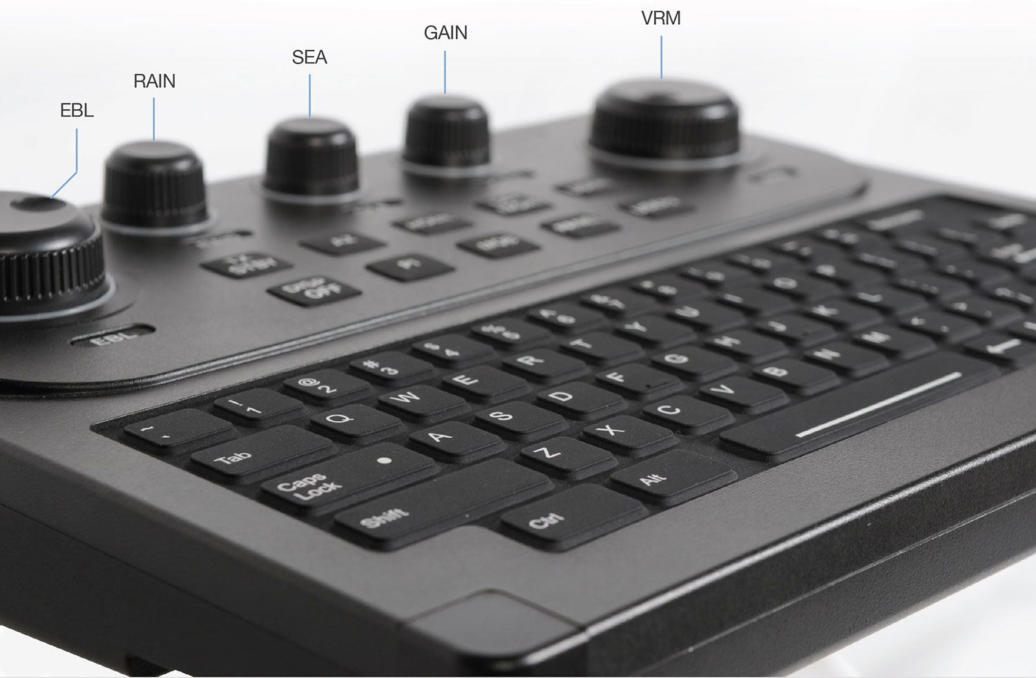
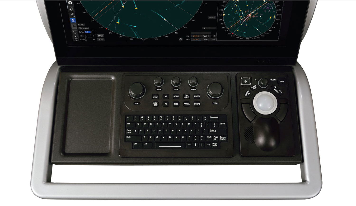
The newly designed full-size QWERTY keyboard is just as comfortable to type on as a desktop keyboard. Response feel keys allow logical and precise operation while backlighting allows typing in low-light conditions with ease. One touch access to EBL, VRM, RAIN, SEA and GAIN is available from the keyboard with dedicated (analog) push and rotate buttons. Ten additional functions are directly accessible, from which two can be assigned to any frequently used function by the operator. Other keys includes the MOB activation, change between day and night and to start radar transmission.

Installing the keyboard can be done by simply connecting the keyboard to the trackball unit. In case of a standalone installation, the keyboard fits nicely into the all new designed console. Even for blackbox installations we have a dedicated frame that supports both trackball and keyboard. The moment the keyboard is connected to the system, backlight keys match the trackball and keys on the display.
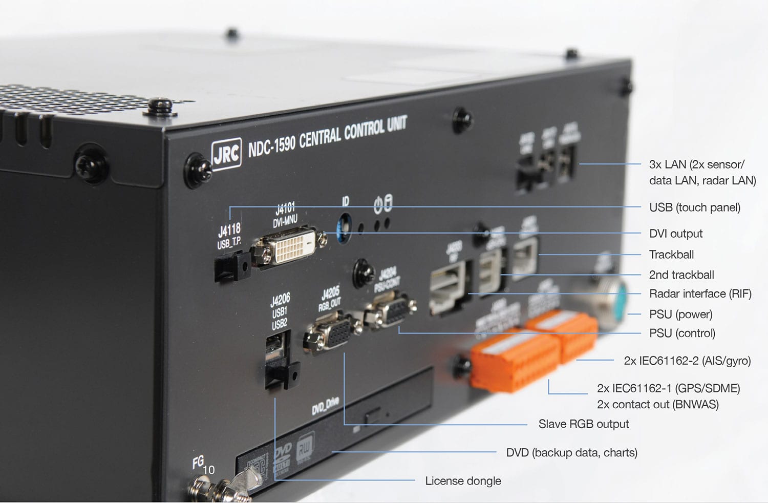
The Central Control Unit (CCU) can be used for your basic interfacing and configuration. A wide range of standard interfacing is direclty available from this unit. The CCU includes two in-house designed Blizzard™ processors, bringing operational performance to a whole new level, especially for the complex tasks running flawlessly in the foreground and the background. Ready for the years ahead.
Also data protection is key for years ahead of safe operation. Every single CCU is equiped with white list type virus protection function by Trend Micro™.
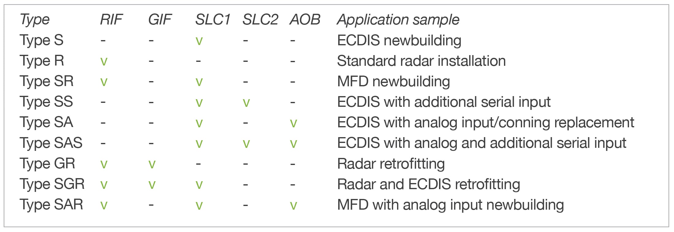
Extending your system by extending the number of interfaces and ports can be done the moment you purchase your system or can be upgraded while at sea. Either way, the junction box with the ability to hold a variety of boards plays a central part. As the MFD is set up to function in a bridge LAN network, you do not need to add for every single product a junction box with approproriate boards, but the data and relevant interfacing are shared over and through the network.
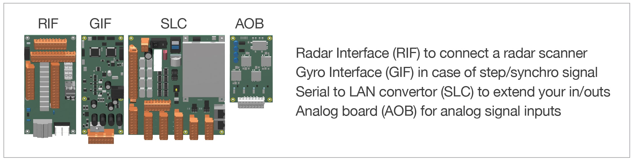
Even the PCBs fitted are thought through. The junction box can hold up to 9 different variations. It can physically hold 2 SLC's. The GIF and RIF are both half the size of the SLC. The AOB is fitted on top of an SLC.
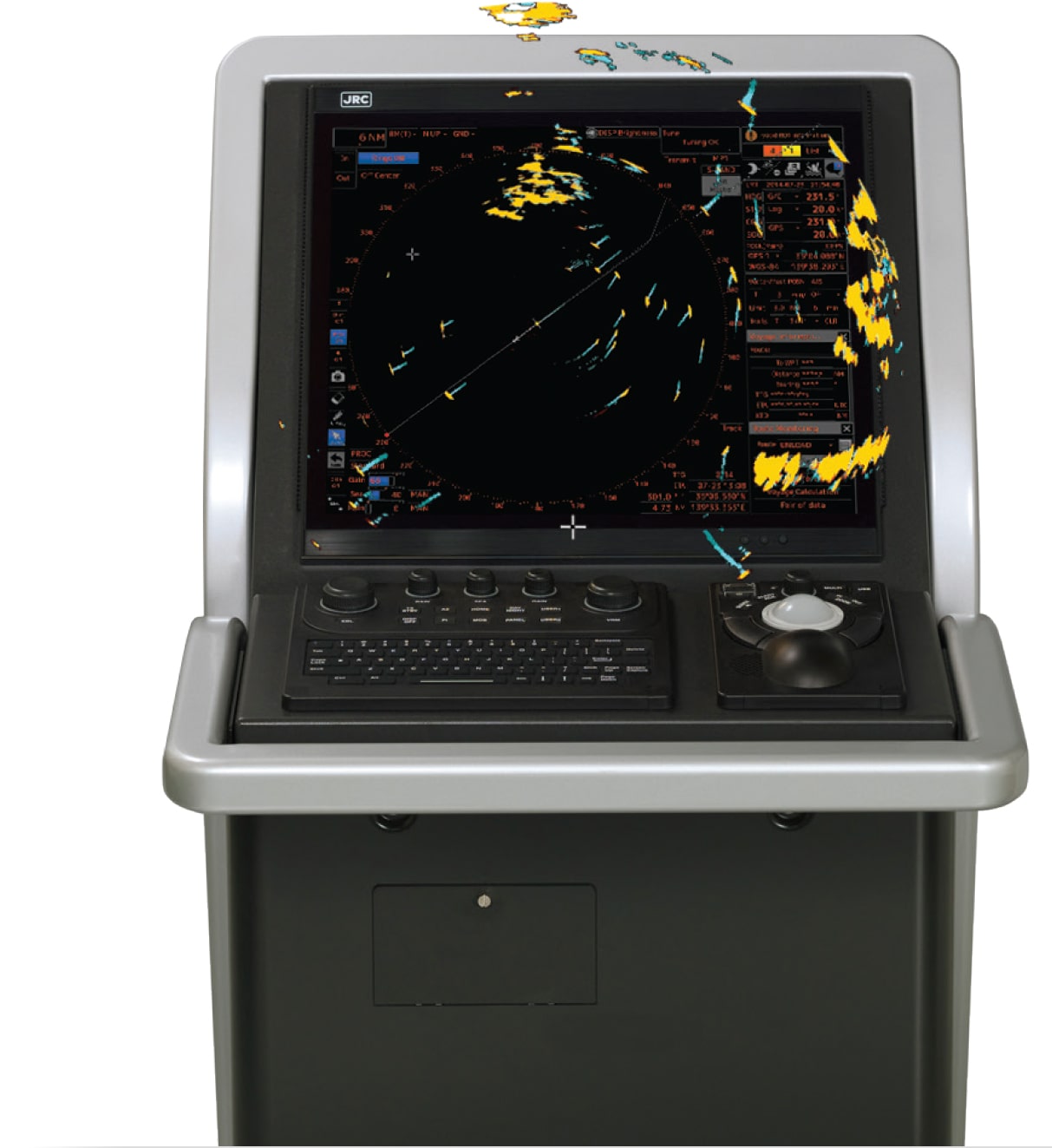
The R in JRC so to say could be easily associated with Radar instead of Radio. Since our humble beginning in 1915 as a radio manufacturer, the company has grown to become a global leader of marine radar systems with many world firsts, having sold close to 400,000 units. To put this astronomical figure into perspective, JRC has, ever since Neil Armstrong set his first step on the moon in 1969, sold 1 marine radar every hour up to this very date.
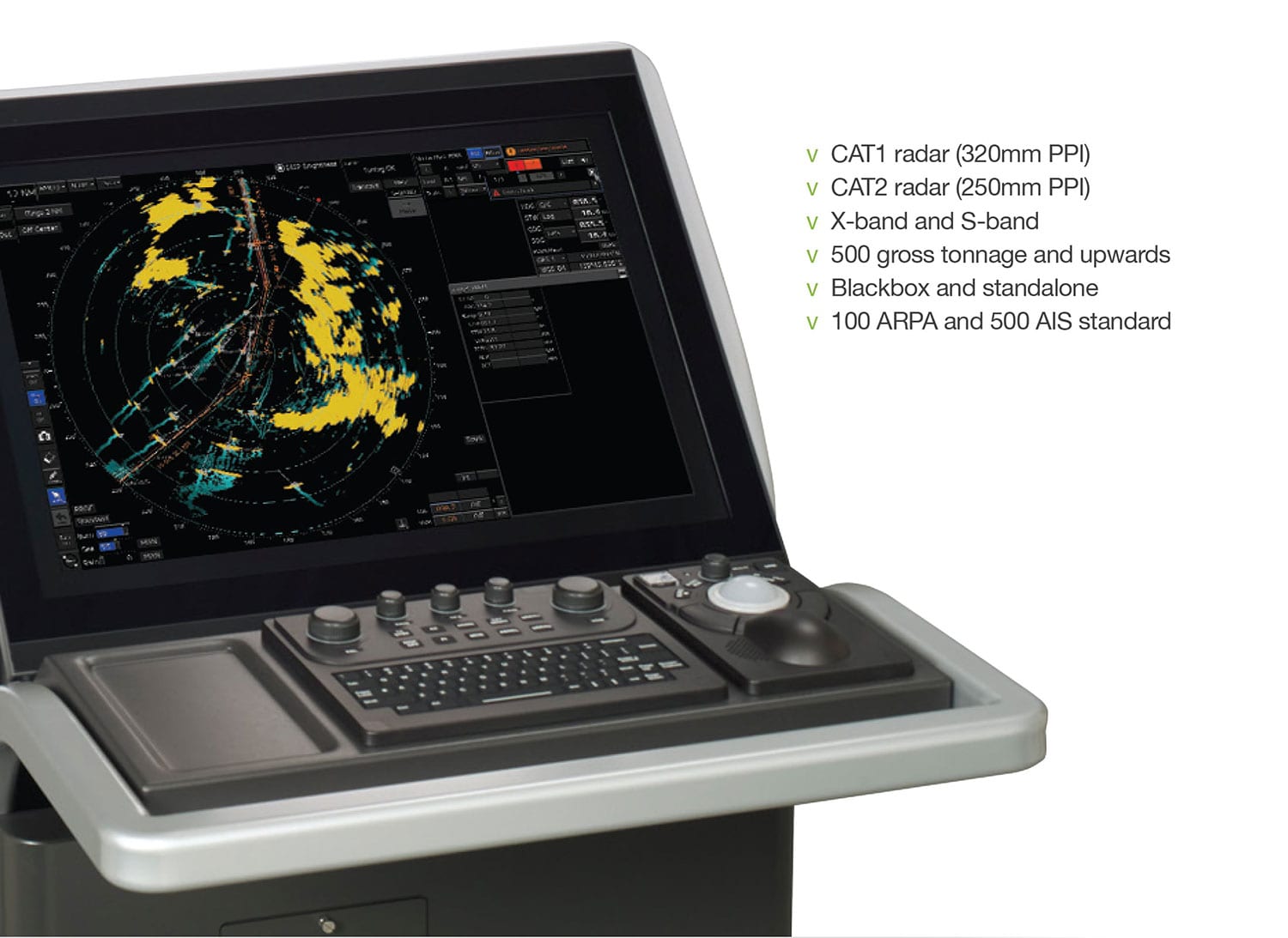
Needless to say, all latest advancements in technology have been put into our newest generation MFD radar reaching a whole new level of performance, designed to seamlessly run radar images faster, even simultaneously, and more efficiently than ever before and integrate a whole new set of functions and features to assist with safer navigation.
JRC has a wide range of scanners available. X-band offers greater resolution and detection of smaller targets, but is subject to interference from rain and seas. S-band radar has a longer range and less interference from rain and sea clutter, but has less sensitivity for small targets. Available as a traditional magnetron type or solid state (S-band), low maintenance scanners, transceiver up or down, various scanner lengths and output power, normal or high speed, many variations are possible, to always have a solution at hand to fit your type of vessel.
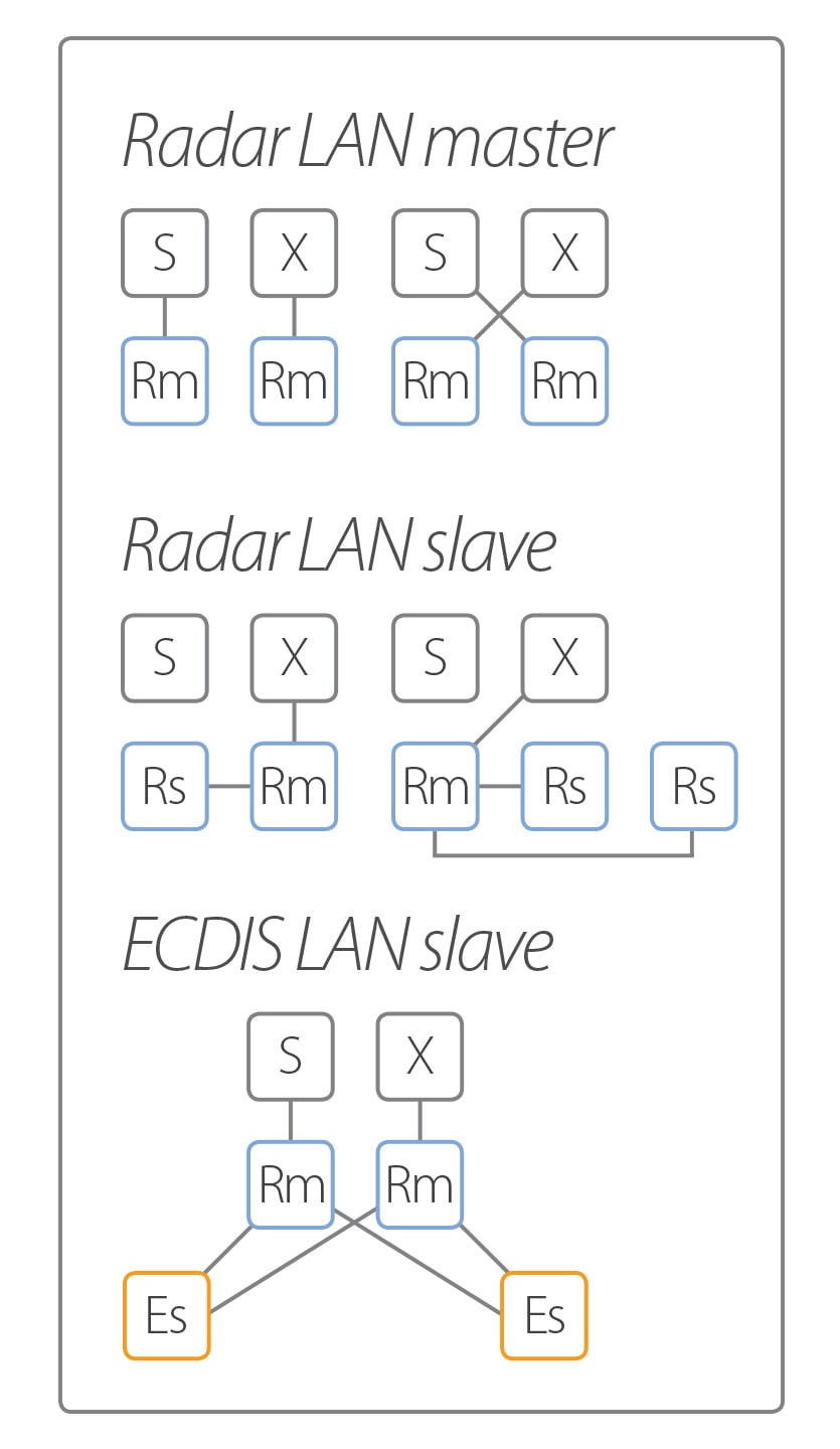
The moment you have more than one radar onboard, controlling any of the radars at any display will be possible with the new MFD. The Central Control Unit (CCU) has one "analog" and two "digital" inputs which allows you to use an external (mechanical) interswitch or a radar LAN interswitch. Blizzard™ allows independent and simultaneous pre and post-processing of radar video. Both analog (scanner) to digital (LAN) and digital to digital can be input on the display.
The radar video pre-processes (GAIN, SEA, RAIN) at the CCU before reaching the display and is compressed with high resolution and transferred via radar LAN to other connected MFD. Post-processing (range scaling and further enhancements) can be done at any display. The external interswitch unit can connect up to 8 units whereas analog video signals are switched externally (away from the display unit). If flag/class requires full scanner control regardless of connected display condition and signal processing, we would like to advise the use of the external interswitch unit for peace of mind. Naturally slave displays are possible however they do not give full control of scanner unit.
Radar overlay on the new ECDIS can be done by the radar LAN. And with the previous generation radar the ECDIS can be installed with a radar interface board to enable this function. The legacy radar models (JMA-9100, 7100, 900B, 5300) are able to interswitch with the MFD.
As a world leader in the design and manufacturing of marine electronics, this latest IMO requirement has been a lot longer in the making than many others, with the first JRC pioneering models designed as far back as 1995 when IMO adopted the initial ECDIS performance standard. Continuing the philosophy that has made JRC ECDIS a proven choice from the very beginning, the new models have been designed with a significant amount of user input gathered over years of intensive operation.
Most noticeable upon first introduction will be the perfected user interface, designed with the purpose to create an experience that lives up to the JRC standard of excellence. A very clear picture that takes maximum advantage of the chart viewing area.
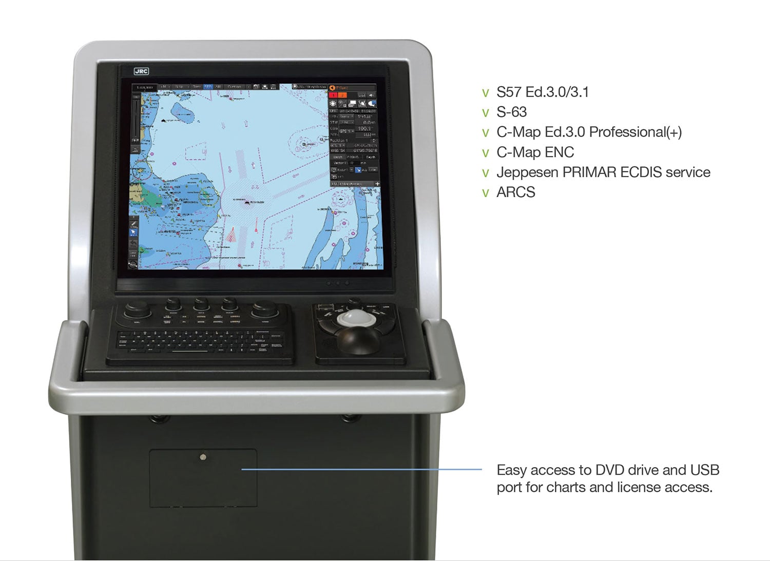
Ex-factory the new ECDIS model comes standard with a pre-loaded range of official, global ENC's and is ready for all well known chart suppliers. Having direct access to the portfolio of ENCs makes it far easier to obtain the data required for passage planning. Also industry standards such as dynamic licensing, PAYS, AIO are available and during route planning and/or while on voyage, weather, tides and piracy information can be seamlessly downloaded through the various services of the chart suppliers.
The minimum required from JRC is a CCU with an ECDIS license and a trackball to operate the system.
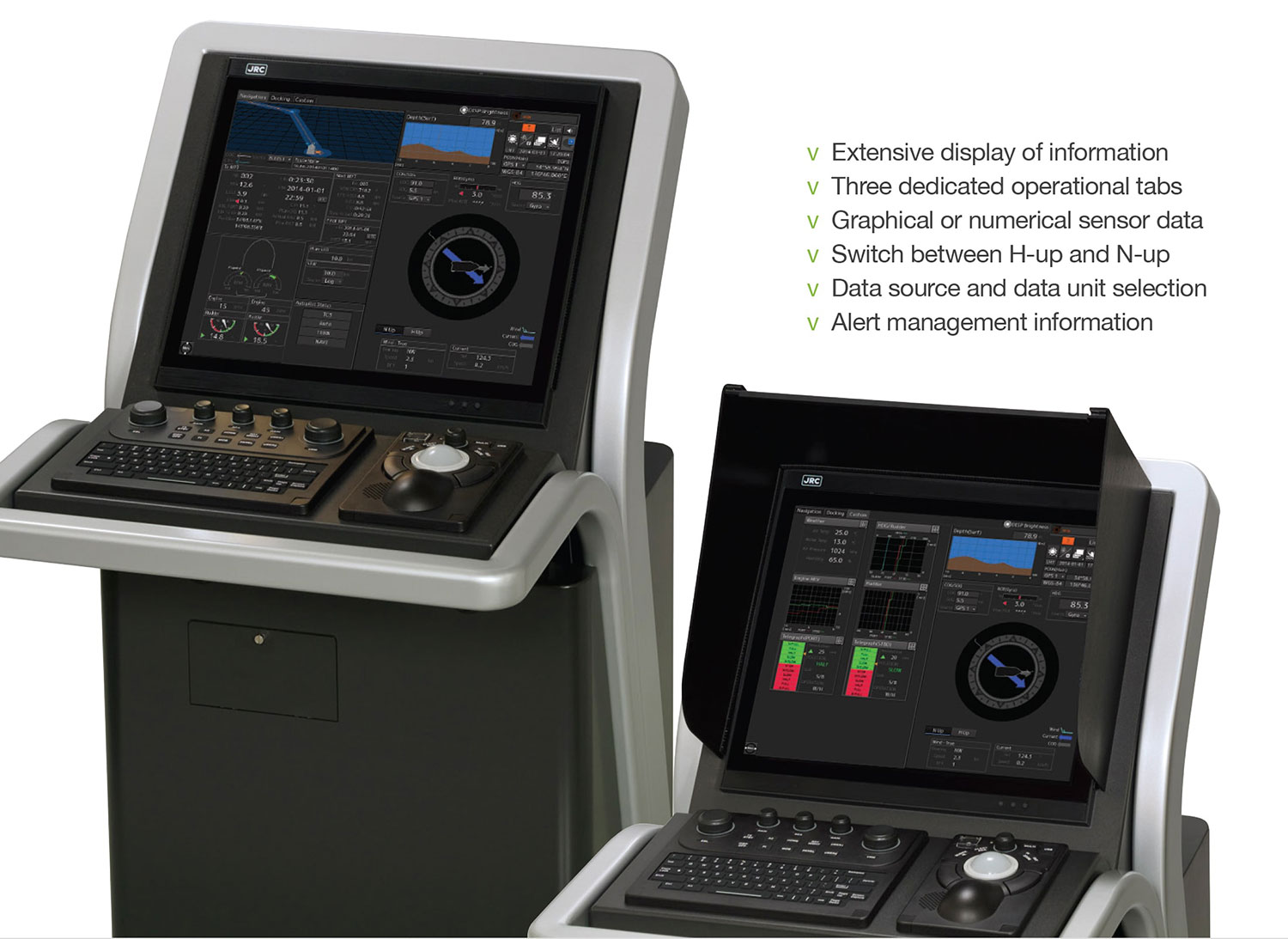
The conning function on the MFD is a giant leap forward. As there are so many things that can be shown, the key ways to optimize how information is presented is in a simple and easy to understand format. Every little detail has been carefully considered.
In general we have three basic tabs which are categorized as voyage, docking and custom, and on every tab the most appropriate information is presented for the officer. For example, the voyage tab has a 3D highway mode, showing own vessel with waypoint information as well as other pertinent voyage related data, while the docking mode shows more precise information in a more task-specific way. Besides these two pre-set tabs, we provide the officers the ability to set their own custom tab.
Minimum requirement for conning is a trackball and a Central Control Unit (CCU). Depending on the number of MFD's onboard you are able to get information through the network. By adding a junction box with one or two Serial to LAN convertors (SLC), this setup will provide you with sufficient interfacing power to suit your needs.
All the information presented on the conning display is built up in blocks. On the user tabs, the blocks can be positioned at the officer's choice. For example, if you have an aft facing bridge the 2D picture of the vessel can be rotated 180° to match your operating manoeuvers as you are looking aft.
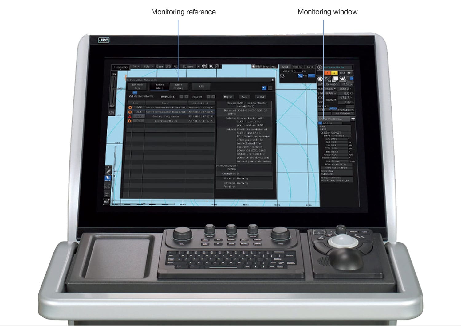
The alert notifications has been deeply integrated into the MFD design architecture having become an integral part for the officer. Alerts are prioritized as "red" alarm, "orange" warning and "yellow" caution. As part of our unified design approach, regardless of which of the functions of the MFD you are currently operating, the alerts are always shown at the top right on the screen. By combining these, easy to recognize colors with the number of alerts that have been generated, gives the operator an instant overview and follow up as required. Click on the any of the three color buttons and it will show a popup list of particular alerts.
Needless to say, from the same top right area you can acknowledge an alarm and even further sort the changing order of alarms according to their relative importance and need of attention. You can also single click to the list showing all active alerts, regardless of their priority, as well as a complete history.
Once you have the alert list open, other alerts and notifications are just a single click away. Think of (send, saved, received) AIS message tray, Navtex, Enhanced Group Calling (EGC) and information reference to your own ship data information.
In general we have two types of information windows available. The first one is the monitoring window used together with the radars' PPI and the ECDIS chart, and the information may include TT/AIS values, wave analysis, route monitoring details, conning blocks. These windows can be displayed at the bottom right corner of the screen in radar. In ECDIS, although, the windows are initially displayed at the bottom right, they can be moved as floating windows.
The second is the reference window, showing specific details retrieved from AIS, Navtex, EGC, alert and own ships AIS information captured at that specific moment in time. This information window is a temporarily reference that includes the AIS message tray, NAVTEX, EGC, alert and own ship AIS information. This allows you to simply view information at a glance and actively view, acknowledge and prioritize alerts.
The MFD provides a rich suite of objects, which you single-handedly can enter, move, insert and add on user maps. Up to 500 maps can be saved. The user map is linked to the chart, and even if there are multiple user maps, you can easily select or merge. The objects consist of mariners marks, symbols, lines, areas and texts. From buoys to buildings and harbors to seabed signals, JRC’s new ECDIS has 65 categories which includes close to 450 graphics instantly available for endless possibilities.
User maps will be compatible from previous generation ECDIS to the new MFD. On the new MFD we have significantly increased the library of drawing tools, which prevents user maps on the MFD being exported to previous generation models.
The patented Constaview™ is realized through the use of two in-house built high-speed Blizzard™ processors. All information gathered by the radar is fully processed within a few milliseconds before being displayed, generating a smooth image rotation. Even changing azimuth mode, the radar image is displayed without any delay caused by the scanner rotation.
Developed exclusively by JRC, TEF™ allows target enhancement relative to the target size. TEF™ works by adding pixels to targets displayed on the radar image and allows a vastly improved degree of discrimination between targets. Sophisticated processing results in a proportional enhancement where the relative enhancement of smaller targets is greater than applied to larger targets.
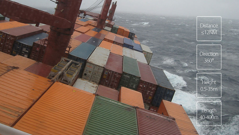
Do you want to have a JRC original wave analyzer without additional hardware? Well, the moment you have installed a JRC MFD, functioning as radar and ECDIS, you will have the unique opportunity to purchase an additional license activating wave analyzer which, needless to say, will be an integral part of the MFD.
Making powerful things simple requires some seriously advanced technologies. The MFD is built for that. The X-band scanner unit detect sea clutter from the sea surface and the incredible performance of the Blizzard™ platform processes and analyzes wave action, which is displayed on screen.
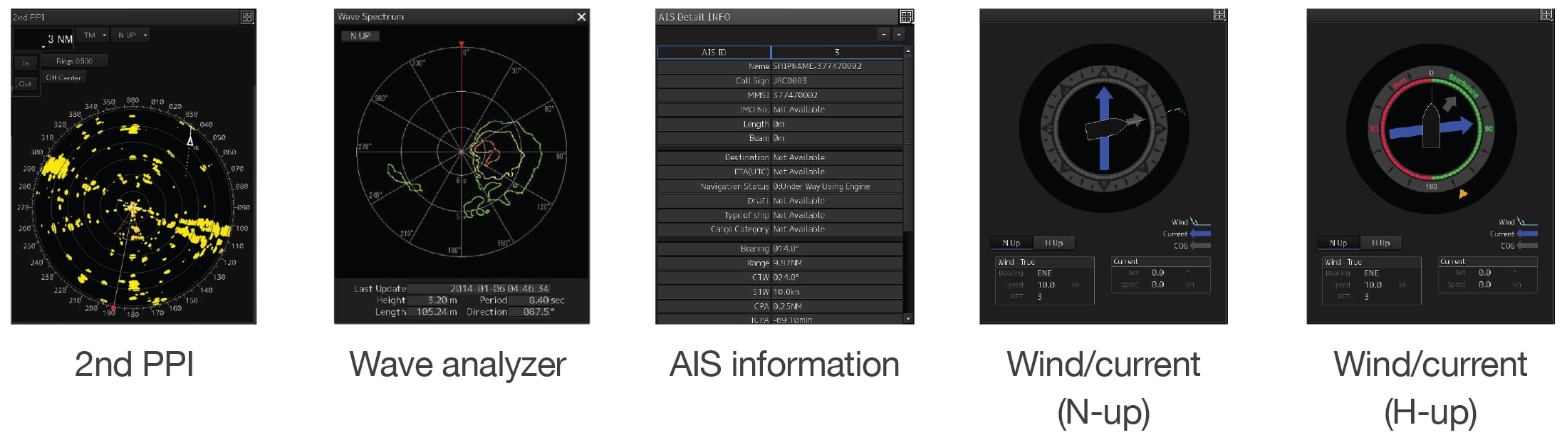
The wave analyzer is able to assess wave direction, length, speed and height to essentially use it as a decision support system, delivering true benefit to officers. The wave analyzer can also detect synchronous and parametric rolling, providing the operator with high precision data at hand to adjust the course, reducing human and hull stress from the impact of the waves. By setting the course with minimum impact allows for increased safety onboard, saves fuel and for example avoidance of container loss.
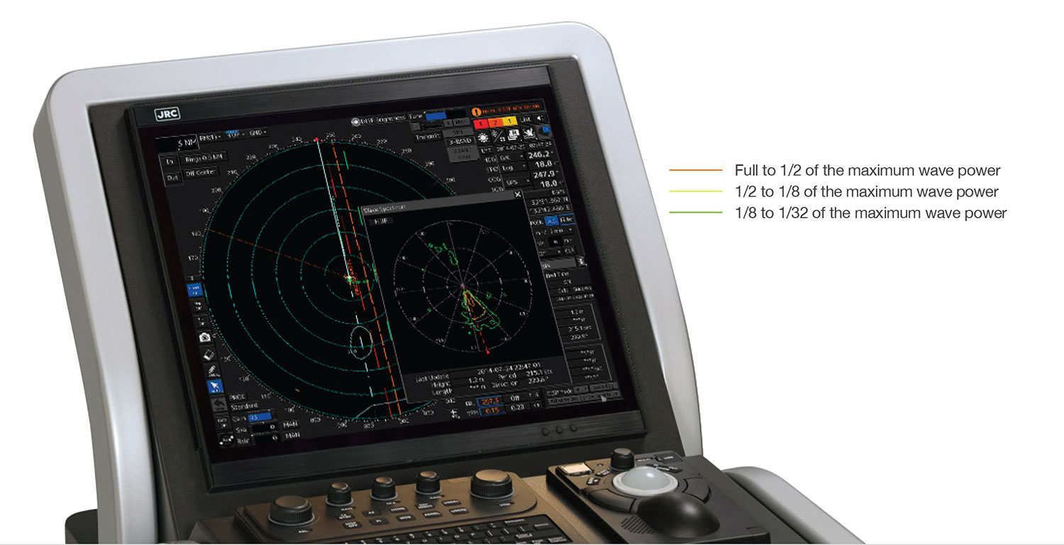
The wave spectrum can be displayed as an information window, to be able to see instant results of the wave analysis. This spectrum shows three colors which outlines the power of the wave detected, travelling toward your position.
With just a few clicks, operations such as route planning, acquiring targets, switching between the systems or show alarm information are easily available. Navigators will know how to use the new MFD the first time they see it because the hardware and software are designed to work together, seamlessly and intelligently.
JRC engineers have developed an exciting new software approach that offers an incredibly easy-to-use icon based navigation experience with simple menus and dedicated functions. If you already use a radar, ECDIS or conning, buying new license/product will make you feel instantly familiar. That is because every MFD product uses the same icons and shares the way of finding (critical) information. And this can be done at a glance and with just one or two clicks being all that is needed to find certain features.
For one, besides finding these functions at the same location on screen, there is no difference in selecting a range in miles or scale, as it can be done either way with just a click of the mouse, extremely useful when you are in ECDIS mode with radar overlay. Naturally available at any time. But also integration of other equipment is available at the touch of a button. Inside the icon button of the message center shows the number of unread messages, similar to what we today use of on mobile phones, added up from the AIS, Navtex and EGC messages.
If you need help, the MFD includes built-in HTML help functions that support you with various operation methods and inside information instead of the hardcopy manual, instantly available whenever required. Additionally, even help is given in case of alarm. When going through the alarm list, not only the alarm abbreviations are explained, it even gives the user suggestive actions.
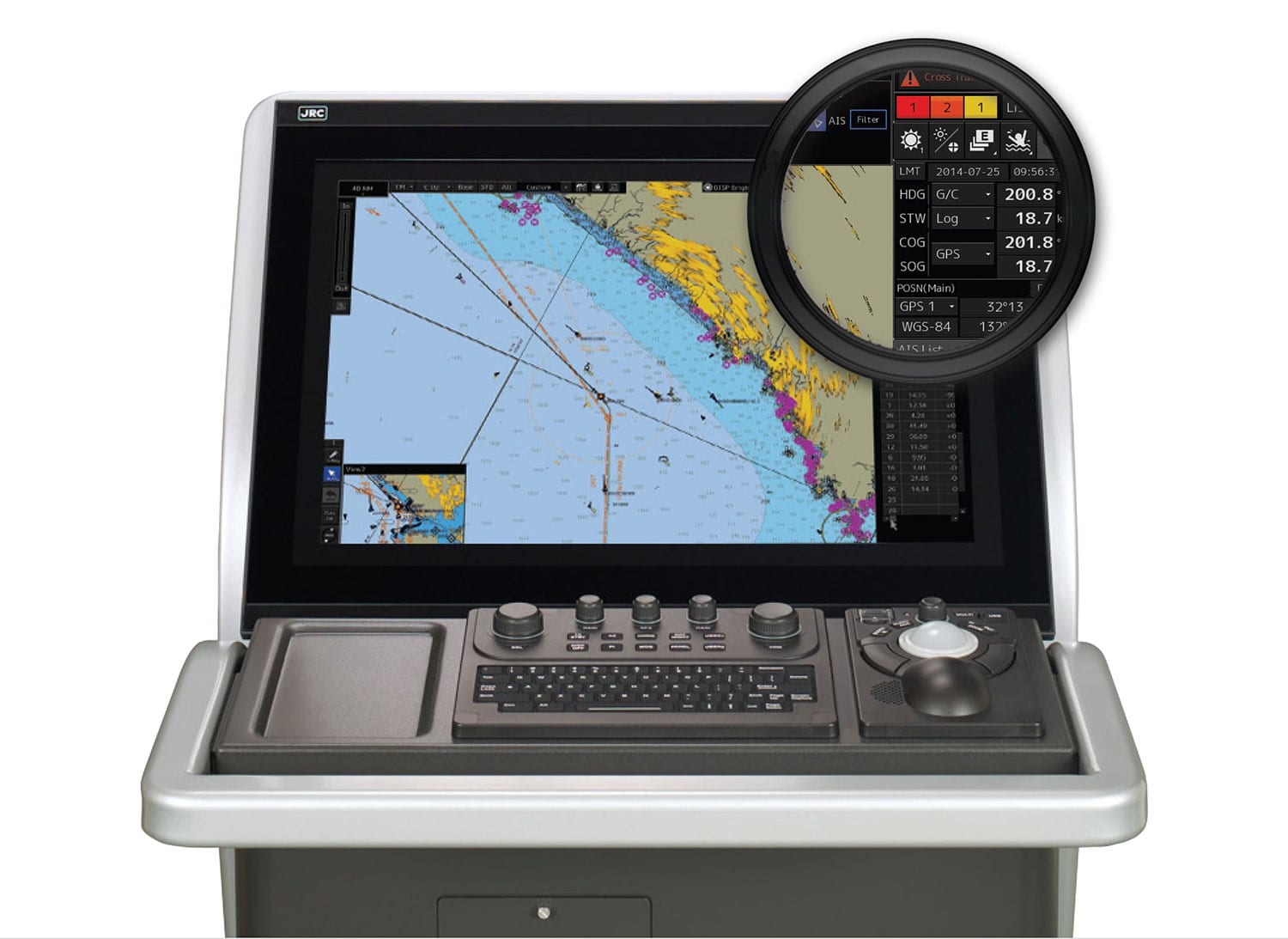
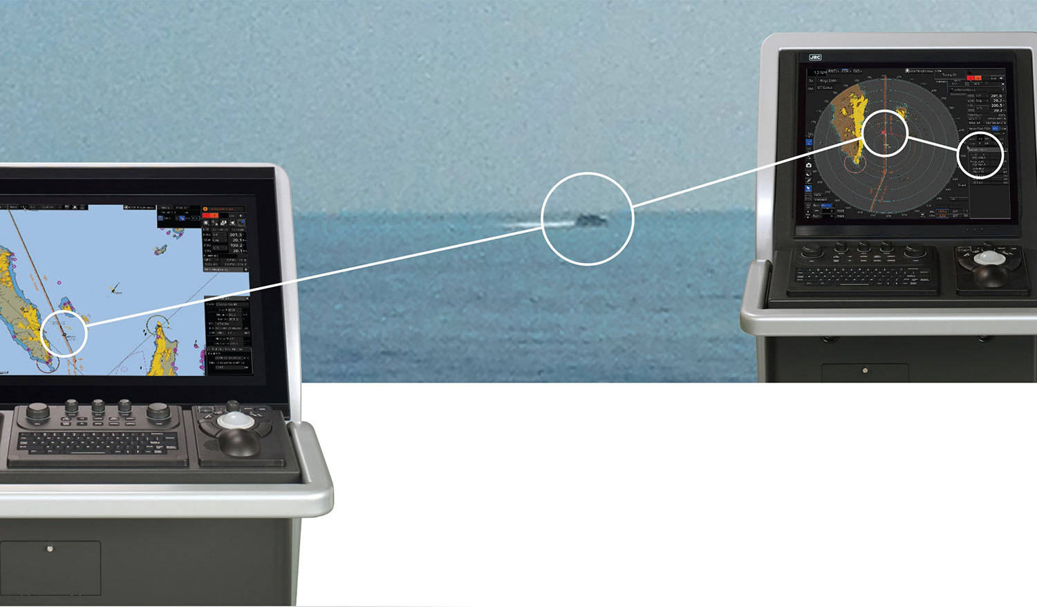
With the MFD development we put high effort on minimizing the number of steps and logic to achieve certain tasks, especially useful for target optimization where in busy shipping lanes you wish to see information quickly and uncomplicated. In case of an AIS and/or ARPA target, and with radar and ECDIS, there is instant information of that specific target simply by “mouse over” on the target.
Right mouse click on the target gives an popup to initiate certain functions and left click to select the target. If you have the TT/AIS monitoring window open, the target you selected is immediately highlighted in the list. And if you would click on (any) of the targets in the list, the target is instantly highlighted within the PPI on the chart. And if the AIS and ARPA target is the same, naturally the MFD combines such information. And expressing danger status with sound, shape and color of a symbol.
When you have the standard target list open, it displays a variety of the most critical information such as ID, range, course, CPA, TCPA and so on. To sort any information, click on the column headings at the top of list view. If you require additional information, simply single press to open an extended window icon.
On the MFD, all information can be found at exactly the same position, think of, find the main menu left bottom, own ship info with dedicated functions such as smart switching, message center and man overboard at the right top.
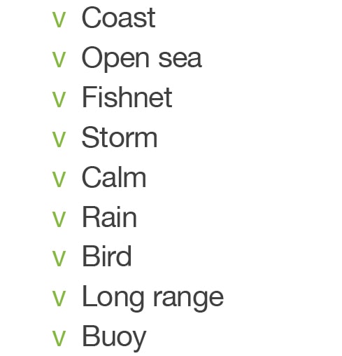
Even for the most experienced officers, obtaining optimal image pictures may be something of a challenge. This requires having a real good sense of radar signal processing and equally well fine tuning of the image according to sea conditions at that moment. To make navigating a little bit less complicated and to assist the officer, JRC has taken away that task by incorporating 9 pre-set values (and 2 additional slots available which can be set by the user) based on decades of experience in navigation.
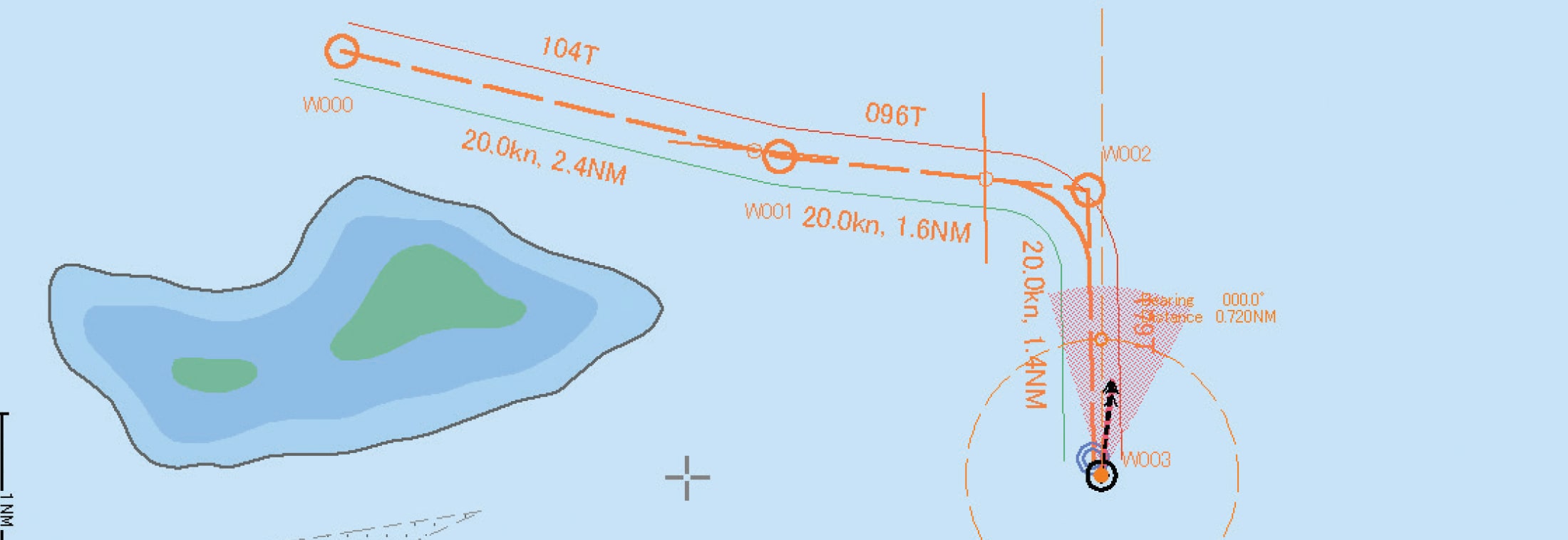
Route planning has been completely rebuilt for our new MFD system. The advanced nature of JRC’s new ECDIS system allows you to plan a route in different ways with extensive flexibility. First thing you notice when you start planning your route is the new menu bar which allows you to do basically anything.
You can use the table or graphic editor or use both at the same time. When you graphically draw your next waypoint it is automatically added to the table editor. And vice versa. Open, edit, save new and existing routes can be done with ease. Up to four routes can be opened at the same time. You can select and move the entire route on screen and even combine routes, and easily exchange the alternative route with the route in progress. Also from the bar you can easily split the chart between single, left-right, top-bottom or as floating view which can be scaled at own convenience. Dedicated buttons allow you to single click to view waypoints as you prefer. Either zoom in on the display with waypoint centered, or display waypoint to waypoint or display the entire route. You can move, insert, add and delete waypoint and divide a leg.
Checking the route data is the most important task after a route has been set, which can be directly selected from the route bar. A safety check window is opened which allows you to check through one by one. By clicking on any of the errors displayed, it will automatically jump and zoom to that particular error, which is highlighted on the chart for immediate attention. And with the safety check window remaining open, a refresh button similar to internet browsers, updates the list to see where you stand at that moment. Automatic sailing is enabled by connecting an optional auto pilot function. After the route is completed, you can save the route. These routes can be used also on previous JRC ECDIS models. But also routes made on previous generations can be imported to the new MFD.
While planning a route, depending on your location and course, the MFD takes the positioning of your FleetBroadband, Global Xpress and VSAT antenna into consideration and alarms if at any point in time the antenna is blocked by funnel, mast or other obstruction. This unique functionality allows for a peaceful, secure start to the route, allowing always-on voyage for updates, chart services and other intelligence which may allow for a safer passage.

We created a storm with our previous processor Tornado™ having delivered over 20,000 radars that included this technology, which have allowed radars to easily perform complex tasks. Now the processor climate is about to change dramatically with our next generation Blizzard™.
The MFD includes the powerful Blizzard™ processor that features advanced signal processing and graphic drawings, regardless of which (19 to 46-inch) display you are using it delivers unprecedented performance - all around. So whether you are browsing through your alarm list, tracking 100+ ARPA and/or AIS targets, planning a Transatlantic route, the MFD with its Blizzard™ processing flies through the most complex tasks with incredible power and speed. Blizzard™ even allows video signals from the scanner to compensate for any cable loss using a digital filter in the frequency domain, useful in a noisy environment or long distance cable run.
The new processing power allowed JRC engineers to build unique functions that perfectly match todays' needs and requirements.
If you want to track a target, you will get a stable vector immediately. That is because that the detected target was already being tracked in the background. This applies for up to 100 potential targets tracked in the background up to as far as 32NM, in "near to far" order. Blizzard™ is always assisting you, even though you do not need it at that moment.
The enormous processing capability of Blizzard™ allows superfast display of the radar picture, even outside the PPI. One range up and down from the range you currently have on display is being processed in the background, allowing for immediate response and display when range is changed. Seeing is believing.
Because of Blizzard™, we are able to display on the MFD two independent radar pictures. The secondary image is processed separate to the main PPI image. The new Blizzard™ processor enables this on a hardware base to display an independently processed radar image. By adding a second PPI it creates another level of awareness for the officers, having the ability to show various ranges, but also to show X and S band on the same display. And the 2nd PPI can be personalized in a number of ways. Adjusting range scales, changing motion and bearing mode and even turn on and off range rings and off center mode. Needless to say, with the Blizzard™ not only a second PPI can be shown, but many processes are run in the background to optimize the user experience of viewing the right information at the right time.
While being in shipping lanes or on busy open waters, it could happen that the target you are tracking is outside your visible area. Blizzard™ continues to track these targets many nautical miles outside the circle. Simply select a starting point and drag the cursor outside the PPI to track zoom on a separate window. And the tracking zoom continues to follow the target until you close the window.
With the section zoom you can flexibly select a part of the target or a specific area within the PPI which you want to have a closer look at. This selected part will be shown on a separate window keeping a complete picture.
The MFD can be part of an Integrated Navigation System (INS) and approved as such that holds (chart) radar, ECDIS, conning and AMS functionality. With these functions combined, achieved through full integration with onboard sensors, it allows centralized monitoring by a bridge network, navigation monitoring for prevention of collision and grounding. Also highly accurate navigation control functions as Track Control System (TCS) provide safe navigation and effective bridge management.
Displaying the operational status of your system is a key requirement for INS regulations. On the MFD you are able to bring up a dedicated system configuration overview which allows you to visually see which equipment is connected and by use of simple color (like green or red) to see at a glance the status of that very equipment. But also functionality and network redundancy are just as important. In the unlikely event one workstation fails another can take over and a dual LAN network means redundancy.
Besides that, a built in self-diagnosis program constantly monitors all the system functions, displaying a warning message onscreen at detection and issues a warning sound. The system function test can be done at any time, even during normal operation.
Needless to say, the MFD is fully complying with various IMO regulations.
IMO requires 45 sec of continuous power supply during the switch from main to emergency source. The MFD supports a wide range DC input to keep the system in full operation in case AC power fails. Back up for radar scanner depends on scanner motor, whereas AC scanner (X-band, 25kW and S-band) requires an external UPS, the DC scanners (10kW X-band) can continue to operate and keep transmission/reception by DC power. AC scanners however fed by DC power will not be functional as radar but will perform route monitoring required for one of the mandatory tasks of INS.
For non-IMO installations or for additional back up arrangements in case of extraordinarily unforeseen circumstances, we have for the MFD an (optional) small external UPS battery available enabling correct shutdown after complete blackout. The UPS unit can be installed as industry standard on the DIN rail (also available on the rear panel of our new standalone unit).
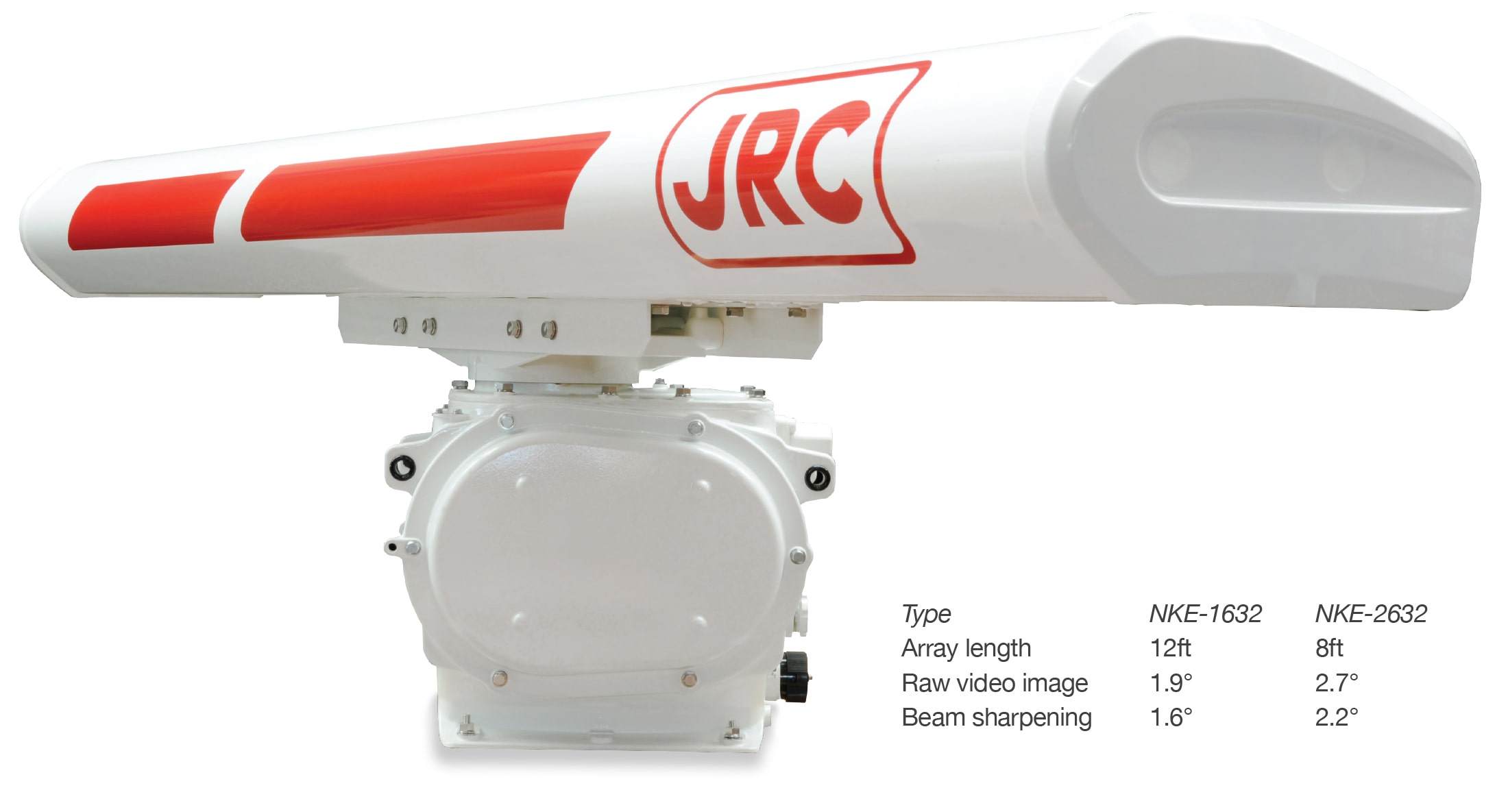
New technology has been added to the scanner lineup which was traditionally always magnetron based. Back in 2008, JRC was the world first to receive MED approval for Solid State S-band with a 12ft antenna. Following many successful installations on a variety of vessels sailing in different parts of the globe with outstanding feedback, we are introducing the second generation Solid State S-band scanner, which will be available in an 8ft and 12ft variant.
Another world's first with its MED approved 8ft Solid State S-band scanner, available in normal and high speed version. This much more air shippable scanner it is smaller and lighter than the original 12ft scanner. At the same time we also introduce a new 12ft variant, featuring common parts such as TX/RX board and processor.
With the price gap between Solid State and the magnetron versions becoming significantly reduced as production increases, the cost saving by not having to regularly replace a magnetron is clearly evidenced.
With the new scanner we also introduce beam sharpening which is made possible through our new Blizzard™ processor. Minimum IMO requirement for horizontal beam width is 2.5° and after beam sharpening, the target discrimination is astonishing, even in short range with two targets which are side by side.
Every product in our new line up is individually available following minimum [IMO] requirements as a cost effective solution and is at the same time expandable by use of optional software and hardware packages to create a highly flexible model. The moment you have purchased two or more products/software licenses it automatically becomes a Multi Function Display and you are able to see the information you want by use of smart switching.
If for example, you have purchased a new Chart radar, to evolve into a full Multi Function Display you can add an optional ECDIS or conning software license, while keeping the standard user interface throughout all the products, with same default logic and design elements.
You do not have to buy a new JRC product to have one that feels new. We will make it easy to update your existing equipment onboard and also gradually make various packages (additional hardware may be required) available that include among others, functions such as weather routing, wave analyzing, RMS and VDR playback.

Visit our website regularly for the latest updates.
Contents are subject to change without notice, some functions are optional or may require a future software update.